3D MPR
The Use Multi Planar Reformatting (MPR) ![]() icon reconstructs two-dimensional views of a series after creating a three-dimensional volume. Users are able to change the layout, view modes and view the viewing angle in the MPR view. The system allows users to activate Slab MPR in MPR View; users can also select MIP (Maximum Intensity Projection), MinIP (Minimum Intensity Projection), AveIP (Average Intensity Projection) and VR (Volume Rendering) in addition to slab thickness for the image. The MPR reconstruction is activated by clicking the MPR toolbar when the user opens a study, which launches the MPR into the viewport. A progress bar is displayed while the series is loaded in the MPR mode. According to the viewing protocol, each viewport can have its own MPR/Slab viewport with an MPR reconstruction of a different series.
icon reconstructs two-dimensional views of a series after creating a three-dimensional volume. Users are able to change the layout, view modes and view the viewing angle in the MPR view. The system allows users to activate Slab MPR in MPR View; users can also select MIP (Maximum Intensity Projection), MinIP (Minimum Intensity Projection), AveIP (Average Intensity Projection) and VR (Volume Rendering) in addition to slab thickness for the image. The MPR reconstruction is activated by clicking the MPR toolbar when the user opens a study, which launches the MPR into the viewport. A progress bar is displayed while the series is loaded in the MPR mode. According to the viewing protocol, each viewport can have its own MPR/Slab viewport with an MPR reconstruction of a different series.
Note that in MPR mode, the Setup Layout Within Viewport tool is disabled. In addition, MPR will not work on framesets where slice spacing is inconsistent.
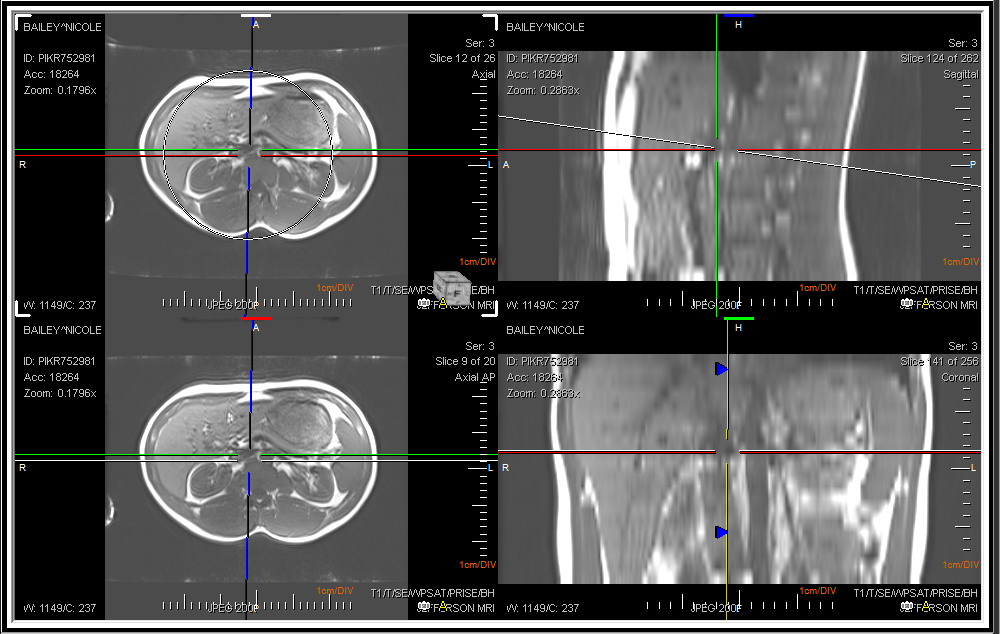
At any given time, one of the Viewports can be selected as the Controlling viewport with a click of a mouse. The remaining three view boxes display the cutting planes related to the three axes in the controlling viewport. All three axes are joined in the center. The Oblique option allows the X and Y axis to rotate. If this option is checked off, the user will not be able to move the axis. The option is checked by default. The horizontal and vertical axes are perpendicular to each other and make up the double cutting plane. The third axis is independent of the other two axes and can be rotated around the center point, calle the single cutting plane. As the cutting planes are rotated and translated, the remaining three view boxes update to reflect the new cuts. While the Vertical axis is used to rotate the image across the y-axis, two slide bars at the right hand and at the bottom of the image can be used.
The Oblique cube functionality is only available in 3D mode.
The sliding of the mouse at the bottom slide bar will rotate the image on the y-axis. Sliding the mouse on the slide bar at the right rotates the images on the x-axis. The rotation is visible in the three attached view boxes.
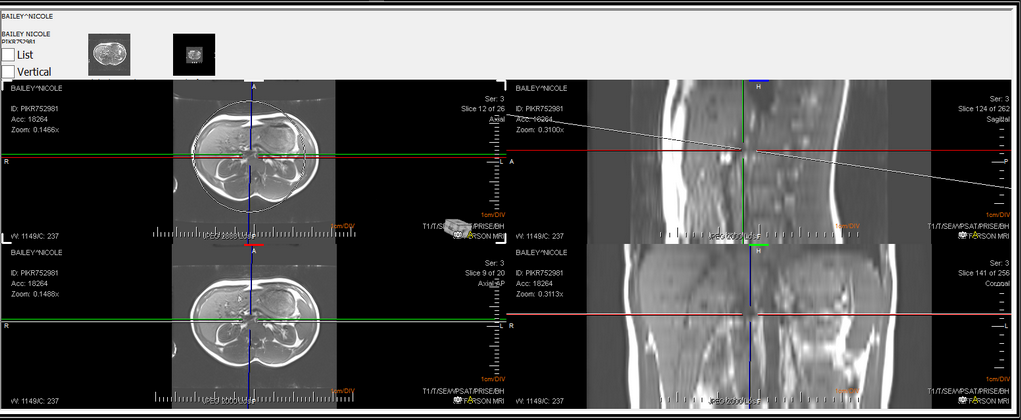
The MPR mode allows to view the image in three views i.e. Axial, Coronal or Sagittal. If the user wishes to perform an operation on the image in one view, the change will be visible in all the three views simultaneously. To scroll through images, simply use the central wheel button of the mouse.
While in MPR mode, a limited set of tools are available from PowerReader which can be used to modify the images within the view boxes. The user can Select, Drag, Zoom, Pan and Window/Level the image. The users can choose to invert the image, Mirror or rotate the image. There is also the option to Measure Tool, Measure Angle, Point of Interest, Annotation Text and use the Region of Interest (ROI) tools. The Create Path tool can be used to show a step by step snapshot of the image at specific 3D points. The Create path tool is described in detail in the section How Do I Create a Path in 3D MPR.
To draw an ellipse, rectangle, or path, press the left Ctrl key and the left mouse button simultaneously.
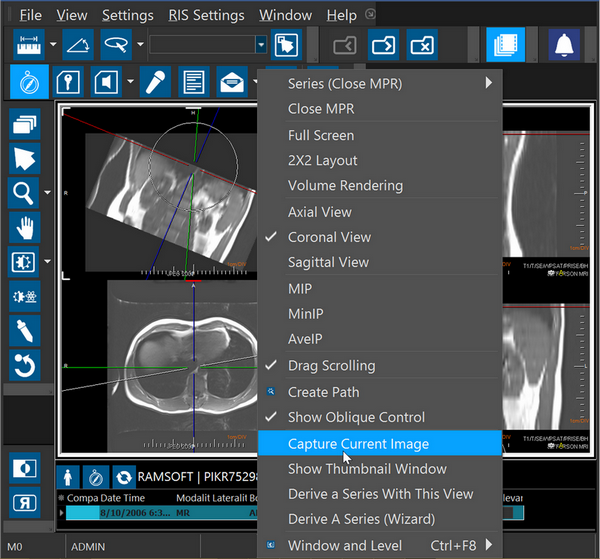
Various tools have been provided in the right-click menu of the MPR mode.
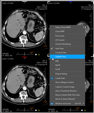
Choosing the Close MPR option exits the MPR mode. The Series option allows the user to select a different series for view. The user can select to view either an Axial, Coronal or Sagittal view of the image.
The various types of intensity projections MIP, MinIP, AveIP or VR can be selected from the right click menu. If you wish to apply an intensity projection (e.g. MIP), right click and select the intensity projection. Selecting the intensity projection will allow you to see the slab width on various other views which can be manually adjusted.
To adjust the slab width, click and drag the dotted lines on the image to adjust the slab width. The cursor will change to a small hand symbol when the slab width is being adjusted.
The adjustment of slab width is in real time i.e. you will see the impact of this change in other view boxes while you are adjusting the width in the current view.
The Display Option menu has two options in a sub menu. The Show Scale option will turn On/ Off the scale on the right and at the bottom.
The Display 2D Text option will turn on/off the text displayed inside the image. Full Screen option will allow the image to fill the screen. This will allow the user to view only the selected image.
The Oblique option allows the X and Y axis to rotate. If this option is checked off, the user will not be able to move the axis. The option is checked by default.
Choosing the Drag Scrolling option disables the various axes and allow the images to be scrolled if the user clicks and drags the mouse.
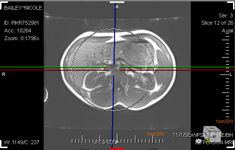
The Capture option captures the image and saves it on the top of the viewports. It captures a single image according to the view the user chooses.
When the current image is captured, by default the captured image appears on the top of the viewports and in the Thumbnails section in the Patient Explorer.
At this point, the view has not been saved. To save the view, choose the image and right click on it to choose the Capture option again. This will create a new series in the patient explorer.
The Derive a Series With This View option will create a new series based on the image being seen.
Choosing the current image will only create a series from the current image. There is the option of creating the series as a screen shot (with all annotations) or as DICOM (without annotations). If you wish to create a series out of the series of images, choose the second option and add the desired options i.e number of images, spacing between images, slab thickness etc.
Once a series has been derived out of this view, a thumbnail will appear on the screen at the top. The thumbnail will be in addition to the original series thumbnail which is from the original series.
If the user wishes to get rid of the thumbnail, they can do so by right clicking on the thumbnail and choosing Delete from the menu. The delete option will not be available for the thumbnail of the original series.
The Derive a Series (Wizard) option allows the creation of a series with the help of a series creation wizard tool. You can choose either an Axial, Coronal or Sagittal view. The rest of the process is identical to Derive a Series With This View option described above.
The Window and Leveling option can be used to perform the Window/ Level image manipulation or to select a window preset for the images.
The Annotation tool can be used to create annotations on various points in the image which might be interesting to the viewer for any reason. To do so, click the Annotation button on the tool bar and enter a value in the annotation bar.
Then elect a point in the image and click to create annotation in the image.
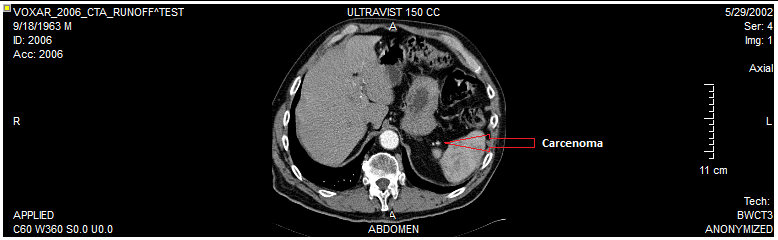
The annotations will be saved on the side with a line directing to the point in the image which the annotation belongs to. You can then capture the image with annotations and create a separate series if desired. To erase the annotation, right click on the image and select Delete. You can also choose to edit the annotation text with the right-click menu.
PowerReader allows users to adjust the viewing protocol for MPR studies. These settings are automatically applied as preferred settings when the user opens an MPR study. To specify settings for MPR, open the drop-down menu from the Viewing Protocol button and then choose View Viewing Protocol's Details.
Once the Viewing Protocol details have opened, click on the Series Setting tab. In the Series Setting tab, you will notice the Series Setting section on the right.
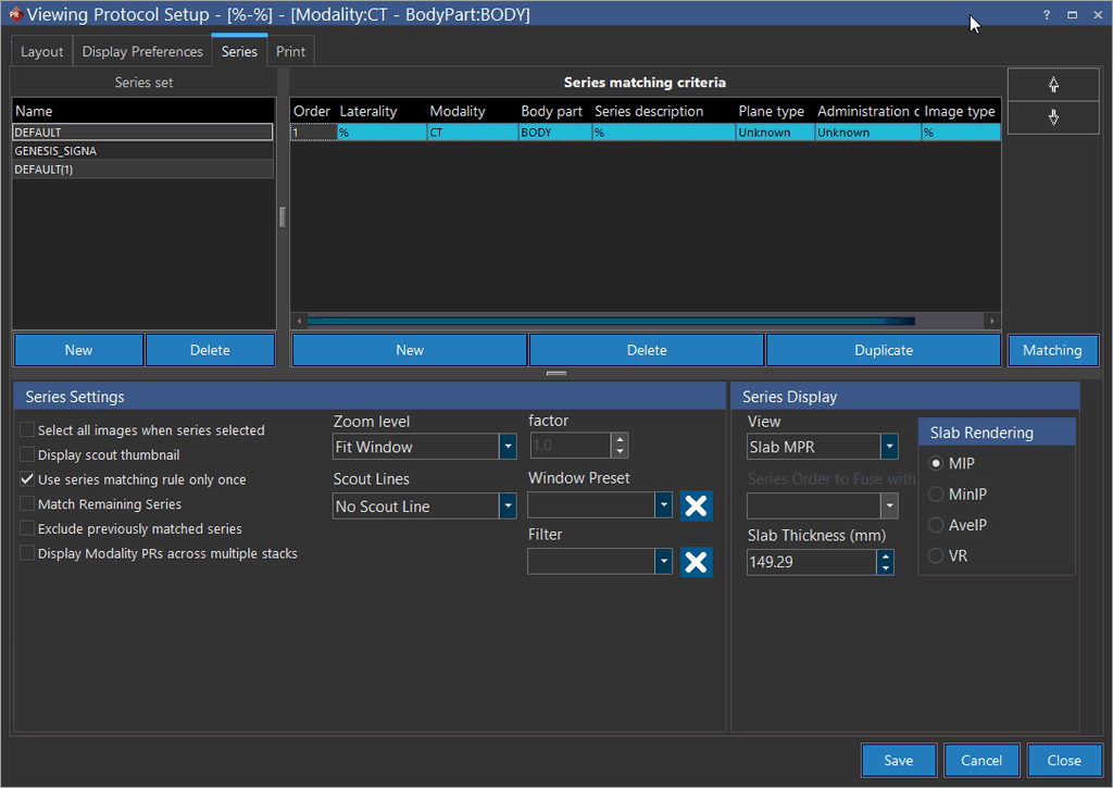
The Series Display section with the View drop-down menu is used to create rules for a Fusion (2D), MPR or Slab MPR series. The rules can be saved as a part of the viewing protocol like any other rule. The 2d option is the default option and used when the study being shown is not MPR series. This will be the default view in most cases. The MPR option will be used when displaying any normal MPR series. The Slab MPR option will be used to create an MPR viewport along with a Slab view. If the user chooses this option, the various rendering parameter options become available to the user. The options are MIP (Maximum Intensity Projection), MinIP (Minimum Intensity Projection), AveIP (Average Intensity Projection) and VR (Volume rendering) and will be applied to the viewing protocol according to the view desired by the user. The Slab Thickness option allows the user to adjust the thickness of the slabs used in the MPR.