Paths in 3D MPR
The Create Path option in 3D MPR is a powerful tool which can be used to highlight particular points in an image and create an MPR view out of just those points. This can be very useful in studies where the user will like to expand certain images in a series and view them in detail.
Creating a path in 3D MPR
To create a path in 3D MPR, follow these steps:
- Select and highlight the image in a series where you will create a path.
-
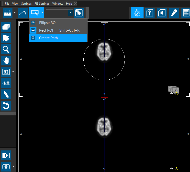
Choose the Create Path option from the right-click menu or the ROI option in the tool bar menu at the top.
-
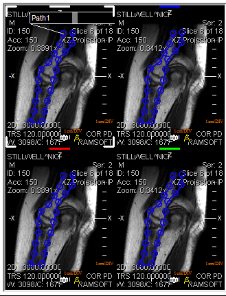
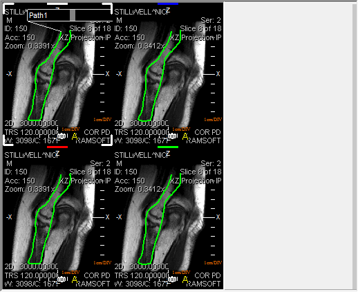
Click and drag the left mouse button while keeping the left Ctrl key pressed, to draw a line over the desired area. A green line is drawn on the 3D model and the other series will also display blue lines where the path is in respect to the 3D model. To edit the path created, click on one of the blue circles which constitute the path and press the left-click button to edit the path.
- Right-click on the newly created path. A sub-menu will open up.
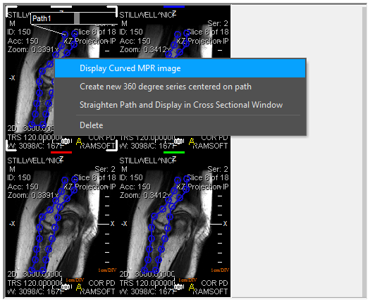
- There are several options available that relate to creating an MPR extract: Display Curved MPR Image, Create new 360 degree series centered on path, Straighten path and Display in Cross Sectional Window, Delete or Edit.
Extracting a Curved MPR Image
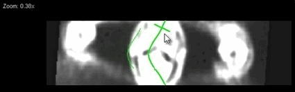
The Display Curved MPR Image option extracts the area selected and creates a Curved MPR. This option creates a slice of the image and displays it on the viewport.
It is possible to find the distance between two reference points in the curved MPR by selecting the Display Curved MPR image option and then pressing Ctrl+Double-Click + left mouse button to find the distance between two specific reference points on the curved MPR.
There is a four step process which requires the following actions:
- Create a path by selecting the option Create Path.
- After the path has been created, click on Display Curved MPR image.
- Once the path has been created, press Ctrl+Double-Click the left mouse button to create a first reference point for measurement.
- Press Ctrl+Double-Click + left mouse button again to create a second reference point for the measurement.
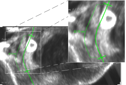
The distance between the reference points will be displayed in centimeters. You can change the reference points by sliding them up or down the path and create further reference points to view distances between them.
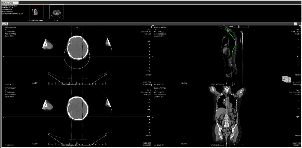
Creating a 360 degree series centered on the path
Choosing the Create new 360 degree series centered on path will extract the area selected and create a Curved 360 degree MPR . Choosing this option will open up a sub-menu.
The user must choose the number of slices/steps and the increment in degrees for the angles of the slice. Clicking OK creates a series and places it above the viewport. As in the above example, the new series at the top contains ten images or slices.
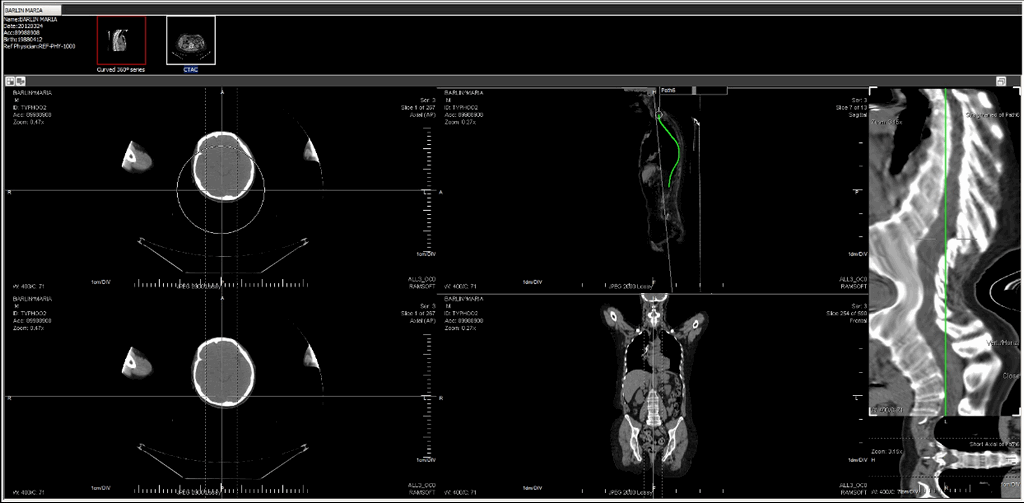
Extracting a cross-section MPR by straightening the path
Choosing the Straighten path and Display in Cross Sectional Window option straightens the path and creates a Cross-Sectional extract. After choosing this option, a cross section MPR displays the area chosen by the Path line (green line) in a separate Viewport next to the image.
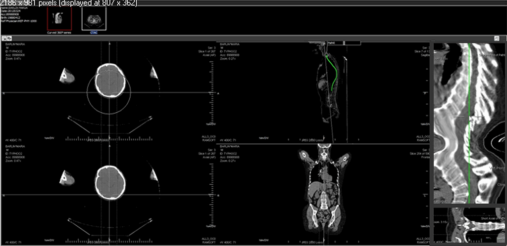
It is possible to find the specific measurements of a specific section of the straightened out path. This is a three step process which is done by pressing the left Ctrl key and double-clicking the left mouse button on the scale to create reference points.
Clicking and dragging the mouse over the cross sectional MPR will allow the viewer to see the slices as per the tolerance level.
If you opt to slide the mouse over the straightened out path (which might be in Sagittal view), the bottom section will display that particular cross section slice in another view e.g. axial.
-
The user must create the straightened path.
-
The user must press Ctrl + Double-Click on the left mouse button at one specific point in the scale to mark it as the first point of reference.
-
The user can then press Ctrl + Double-Click on the left mouse button on another point in the scale to mark it as the second reference point.
-
The distance between the two points is displayed in blue (as shown in Step above).
-
If you wish to adjust the distance between the two reference points, you can do so by clicking and dragging one of the reference points on the scale.
None of these newly created series are saved and will be lost if MPR is closed. To save these series, right-click on any series thumbnail at the top and choose the Capture option. Otherwise, choose Close Thumbnail Window option.
-
After clicking capture, the series will be visible in the patient explorer window.
-
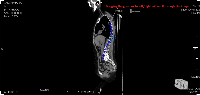
To scroll through the images of a path, click on the gray square in the middle of the path label and drag it left-right. This dragging will allow you to scroll through the images of the path.