Fusing Series
It is often desired to fuse two series into one and view them on top of each other to locate altered metabolic activities at exact anatomical position. This is especially true in the case of CT and PET series, where it is often beneficial to place a PET series on top of a CT series and view the two series together. RamSoft PowerReader comes equipped with the ability to fuse two series and create a new fused one.
Creating a Fusion Series
- Open a study containing the two series to be fused (e.g. a study with a CT and PET series).
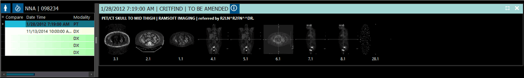
- Open them in a viewing protocol where they are side-by-side (e.g. 2x2).
-
Select the Select Viewport or Drag Viewport to Another Location
 icon.
icon. -
Select either the CT or PET series and drag it on top of the other.
-
After a while, the fusion series will be created in the viewport where the fusion series was dropped (in this case, top left viewport).
-
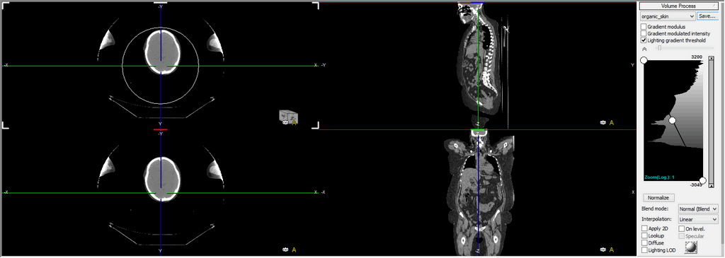
The new fusion series opens in the viewport and contains images from both the series overlayed on top of one another.
-
Using the mouse wheel to scroll through the fusion series will scroll the other parent series simultaneously.
Both series must be in the same view (e.g. both in Axial view or both in Coronal view). Also, in a fusion series, the order of images is always in ascending order.
Fusion Tools
The following options in the right-click menu are present:
-
The Close Fusion option will exit the fusion study.
-
The Series option will allow the user to select a different series for view.
-
Apply 2x2 MPR Layout option will launch the fusion series in MPR mode. As a result, the user will be able to perform MPR options on the series. For further information, please refer to the section What is 3D MPR & How Do I Use It?.
-
The user can select to view either an Axial, Coronal, or Sagittal view of the image.
-
The various types of intensity projections MIP, MinIP, AveIP, or VR can be selected.
-
The Display Option menu has two sub-menu options. The Show Scale option will turn On/Off the scale on the right and at the bottom. The Display 2D Text option will turn On/Off the text displayed inside the image.
-
The Full Screen option will allow the image to fill the entire screen.
Opacity is the percentage of one image from one series vs. the percentage of another image from the other series. As opacity is increased or decreased, images from one series becomes more dominant in view while the images from the other series fade away.
To change the opacity to a desired level so that you can view images form both series, simply right-click on the image. From the right-click menu, choose the Fusion Opacity option.
Click and while holding the left mouse button, move the mouse to the left/right to increase/decrease the opacity if the series. Once the desired opacity is reached, use the mouse wheel button to scroll through the fusion series at that opacity level.
In the example above, the Fusion series on the left is without MPR. The series on the right has a 2x2 MPR layout applied on it. It displays the fusion series in MPR mode with all the various views, i.e. Sagittal, Coronal, and Axial. The difference from regular MPR is that the MPR has been applied to the fusion series rather than just the regular series.
While a 2x2 layout is the basic MPR layout, other layouts are also available. The user can also choose to apply MPR in other layouts such as 1x2. Choose the preferred layout and MPR will be loaded accordingly. The user can turn off the MPR mode by choosing Full Screen option in the right-click menu.
- The Create Path is another option which has been added to the Fusion module. It allows the user to carve a slice out of the image and create a series out of certain chosen 3D points. To do so, choose the option from the right-click menu or the ROI option in the tool bar menu at the top. Draw an area with the mouse. A green line is drawn on the 3D model and the other series will also display green lines where the path is in respect to the 3D model. Right-click on the newly created path to open a sub-menu.
There are several options available. All the choices relate to creating an MPR extract.
The Extract Curved MPR option will extract the area selected and create a Curved MPR. Choosing this option will open up a sub menu.
The user should choose the most suitable option and then click and drag the picture icon on the image. This will create a slice of the image and display it as a series on the top as a thumbnail. If you choose to close the thumbnail view, the slice will be displayed in the viewport.
Choosing the Extract Curved MPR 360 will extract the area selected and create a Curved 360 degree MPR. Choosing this option will open up a sub menu.
The user must choose the number of slices/steps and the increment in degrees for the angles of the slice. Clicking OK will create a series and place it above the viewport. (The number of steps must be greater than 1 and increment in degrees can be up to 360 degrees). As in the above example, the new series at the top will have ten images/slices.
Choosing the Extract Cross Section MPR option will create a Cross Sectional extract. Choosing this option will open the following form.
You can choose the Tolerance value and the measure of tolerance from a drop-down menu and create an MPR cross section. The MPR cross section will display the area chosen by the Path line (in green) in a separate viewport next to the image.
Clicking and dragging the mouse over the cross sectional MPR will allow the viewer to see the slices as per the tolerance level. It will also point the cross section in the other views, i.e. Sagittal, Coronal, Axial, etc. At this point, these series have not been saved. To save/burn the series, right-click on any series thumbnail at the top and choose the Capture option. Otherwise, choose Close Thumbnail Window option.
After clicking Capture, the series will be visible in the Patient Explorer window.
-
Choosing the Drag Scrolling option will disable the various axes and allow the images to be scrolled if the user clicks the left mouse button, keeps it pressed and moves it up or down.
-
The Capture option simply captures the image and saves it on the top above the view ports.
-
The Derive a Series With This View option will create a new series based on the image being seen. Choosing this option displays the following menu.
Choosing the current image will only create a series out of the current image. If you wish to create series out of the current image, you have the option of creating the series as a screen shot (with all annotations) or as DICOM (without annotations). If you wish to create a series out of the series of images, choose the second option and add the desired options, i.e. number of images, spacing between images, slab thickness, etc. If an unusual value is entered in either of the fields (e.g. an impossible thickness value), the system notifies the user of the maximum value allowed.
Once a series has been derived out of this view, a thumbnail will appear on the screen at the top. The thumbnail will be in addition to the original two thumbnails visible in the screen. These two thumbnails represent the original series from which the fusion has been created.
The user has the option to delete the newly created thumbnail by right clicking on the thumbnail and selecting the Delete option from the menu. The option does not appear for the original two thumbnails.
-
The Derive a Series (Wizard) option will allow you to create a series with the help of a series creation wizard tool in which you can choose either an Axial, Coronal or Sagittal view. The rest of the process is identical to Derive a Series With This View option described above.
-
The Fusion Opacity option will has been explained in detail above.
-
The Color Mapping option can be used to apply any particular color mapping to the fusion series.
-
The Window and Leveling option can be used to perform the Window/Level image manipulation or to select a window preset for the images.
-
The Annotation tool can be used to create annotations on various points in the image which might be interesting to the viewer for any reason. To do so, click the Annotation button on the tool bar and enter a value in the annotation bar.
Then select a point in the image and click to create an annotation in the image.
One of the many features of the Fusion series is the ability to find the SUV value for the image through the Probe tool. The value is found out by clicking the Probe tool in the tool bar on the left and then clicking the image to determine the SUV Value. A small menu beside the probe tool icon allow you to choose various SUV options i.e. SUBbw, SUBlbm, SUVbsa. To capture these values, click the left mouse button to reveal the SUV value and then while keeping it pressed, press the right mouse button. This will create a tag that will display the SUV value. Capturing this image from the right-click menu will create a new series which can be saved into the study as well. For further information, please refer to How Do I View Density Information? section in the manual.
Setting up a Viewing Protocol for Fusion Studies
PowerReader allows users to adjust the viewing protocol for Fusion studies. These settings are automatically applied as preferred settings when the user opens a Fusion study. To specify settings for Fusion studies, open the drop-down menu from the Viewing Protocol button and then choose View Viewing Protocol's Details.
For the fusion study's viewing protocol to be updated or edited, both the parent series comprising the fusion should be visible in the viewport
Once the Viewing Protocol details have opened, click on the Series Setting tab. In the Series Setting tab, you will notice the Series Setting section on the left.
The Series Display section with the View drop-down menu is used to create rules for a Fusion (2D), MPR, or Slab MPR series. The rules can be saved as a part of the viewing protocol like any other rule.
Fusion can be done within a viewport if the series are PET and CT series. In this case the Fusion option becomes available in the View drop-down menu. Fusion series viewport will be created as a result of PET-CT fusion. Choosing the Fusion option will activate the Series Order to Fuse With drop-down menu. The menu has the various PET series with their order number and the user must choose one of them to be fused with the CT series.
If the Series matching criteria has just been created, it might take a few moments for the Series Order to Fuse With drop-down list to update.
Click Finish to close the dialog and to return to the Series Order dialog.
Fusion Registration
When two series are fused, a quick registration is performed to align the anatomy as perfectly as possible. If the registration is not as expected, Fusion Registration allows the user to realign the fused series. This is accessible by right-clicking over a fused series viewport.
There are three options available for Fusion Registration:
-
Automatic Registration aligns the fused images more precisely with a longer processing algorithm as compared to the standard algorithm.
-
Manual Registration allows the user to move the two fused images independently of each other. The user can manipulate the alignment with the blue lines until the desired relationship is established.
To pan the image, click and hold on the large move icon in the bottom left corner and drag until the desired positioning is achieved.
To rotate the image, click and hold on the center most circle and drag until the desired positioning is achieved. Rotating is also available on the other two circles.
-
Align Center Registration uses the positioning of the image centers and aligns them automatically.