Using the Viewing Protocol Wizard
To create a new protocol from the setup wizard, open the Viewing Protocol Setup form View > Viewing Protocols and click the Wizard button.
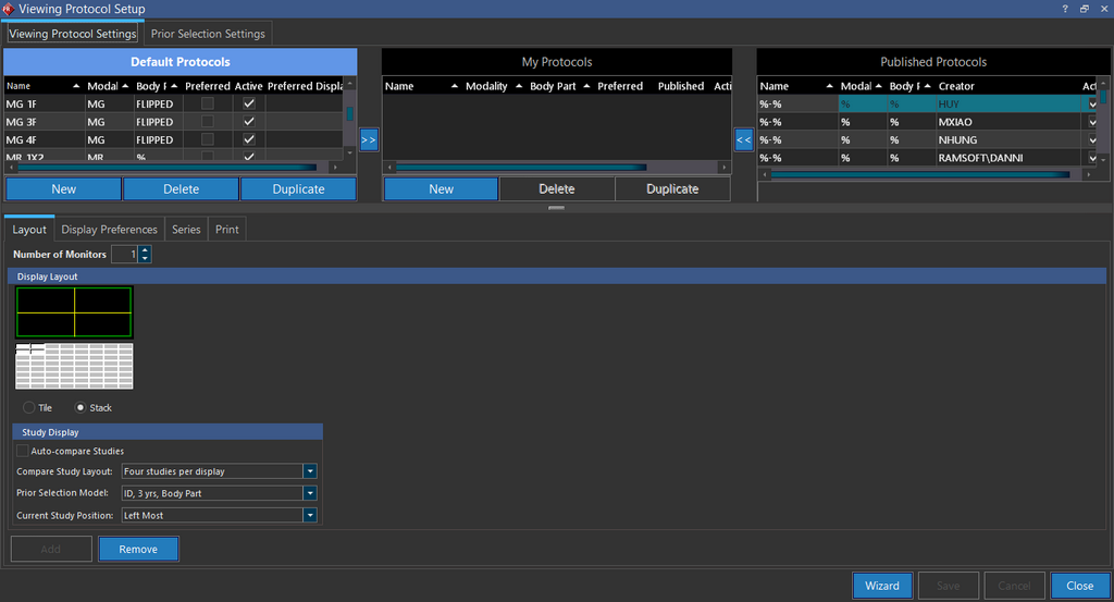
This will open the Viewing Protocol Wizard.
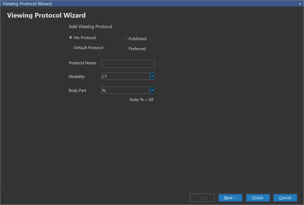
The first item you need to decide is whether this will be a Default Protocol or a My Protocol. If it is a My Protocol you also have the option of checking the Published box. This will make the protocol available to any other users who will like to use it.
The Default Protocol option is available for users with the administrator privilege.
A Preferred protocol is the one which will be applied whenever a study is opened and multiple protocols can be a possible match. The preferred protocol supersedes any other protocol and is applied.
Only one preferred protocol can exist for any given Modality/Body Part combination. If a user sets a different protocol as preferred, the original preferred protocol will lose its preferred status. The Preferred protocols are highlighted in yellow.
Next enter a Protocol Name, as well as the Modality and Body Part this protocol will apply to. Leaving either one of the options as %, indicates that all possible values for that field will be matched by the protocol. The system will look through a list of aliases for body parts and try to match those aliases with the body part entered in the screen above. For example, if a user enters "Head" in the body part field and the body part "Head" has an alias by the name of "Skull" in the Body Parts table, the protocol will also pull studies which have a body part defined as "Skull". This allows the system to search any studies with the same body part defined by a different name. Click Next.
Creating a monitor layout
First choose the Number of Monitors that will be applied to the viewing protocol. You can choose a maximum of four monitors for the viewing protocol.
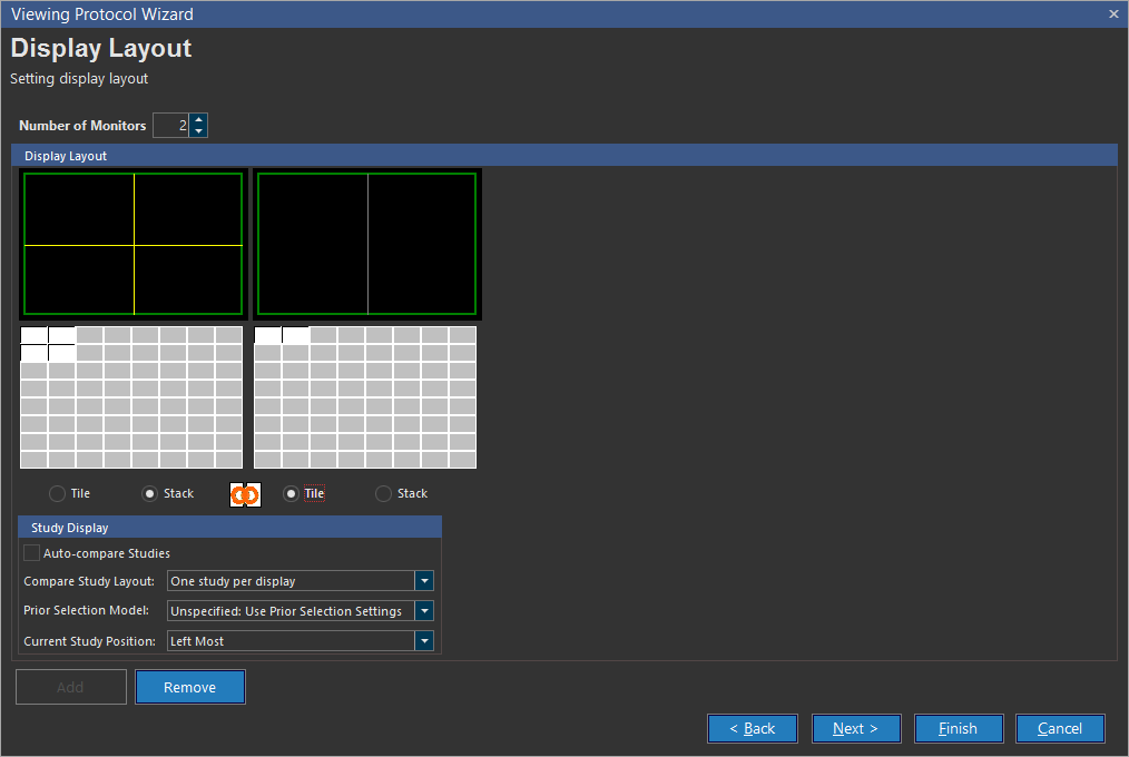
Now you have to decide how many series of images you will like to view at once. How many images of each series will be visible at once is not relevant here, that will be decided later. You can choose to layout of the images on the monitor by choosing the Tile or Stack option and choosing the number of images in the Monitor Graphic above. As a result, each monitor can be tiled or stacked individually allowing you to mix and match as desired. A tile will allow you to view each individual image in the viewing protocol. A stack will put the images in a series into a stack so you can view only one image at a time. Hence you will have to scroll down through images to view them. A monitor can have a maximum of sixty four tiles.
In the example above, a two monitor layout is displayed with the monitor on the left displaying the series in Stack in a 2x4 layout. The monitor on the right will display the same study in a 1X2 Stack layout. A Tiled monitor will only display one viewport at a time. A user can have multiple view boxes in a Stacked monitor.
As you modify these values, the changes will become visible on the Display Layout graphic above the buttons. Each monitor layout can be defined individually.
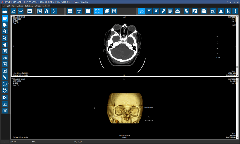
Open in New Viewport
This feature allows you to view the images of a study in a different viewport. You can right click on a series in patient explorer and select this option.
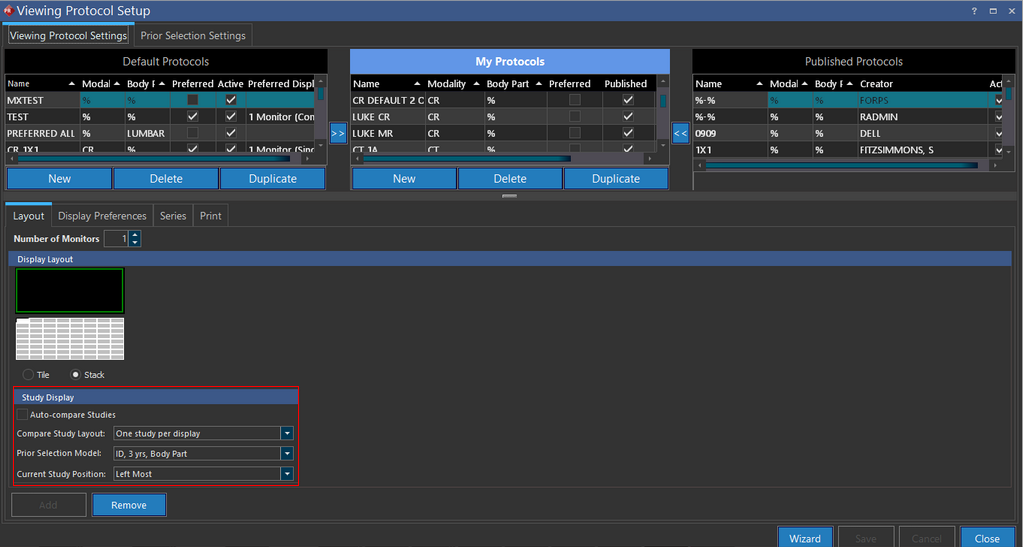
Study Display Settings
You can set up the Study display settings using the Viewing Protocol setup form. When you have a single study and have no related or prior studies, you would not need a multiple study layout. Unless you specify, a Viewing Protocol Study Display assumes that the current viewing protocol is an non-comparison viewing protocol and applies the following Study Display Settings:
- Compare Study Layout: One study per display
- Prior Selection Model: 1d, 3 yrs, Body Part
- Current Study Position: Left Most
Note that you can change these settings anytime by selecting the appropriate option for each of them from the drop-down menu.
Typically this is not the case. Most studies would have related or prior studies with which they are compared. You can customize your Study Display settings and select the Auto-Compare Studies in the Viewing Protocol setup to apply these settings to the Viewing protocol that is setup for a study. The Auto-Compare Studies option allows you to open studies in comparison mode with the Study Display settings as per your requirements.
When you click on Auto-Compare Studies, by default, the viewing protocol applies the following Study Display settings:
- Compare Study Layout: Two Studies per display
- Prior Selection Model: Unspecified:Use Prior Selection Settings
- Current Study Position: Left Most
You can choose how many studies should be displayed in the comparison mode. If you are comparing Priors, you can select a Prior Selection Model from the ones that have been added to the Viewing Protocol.
You can also select the current study's position with respect to the studies that are being compared.
You can now choose to compare four studies at a time using the Compare Study Layout option.
The following are the Study Display options available:


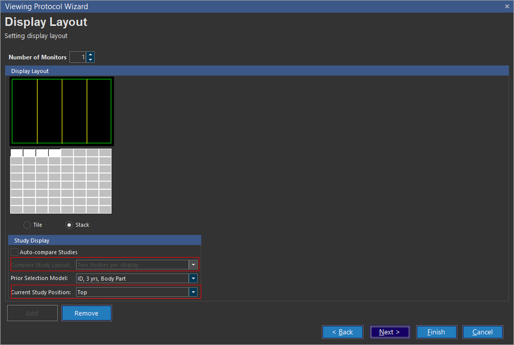
For example in the following screenshot, you can see that a layout for four studies per display has been selected along with other options to compare studies:
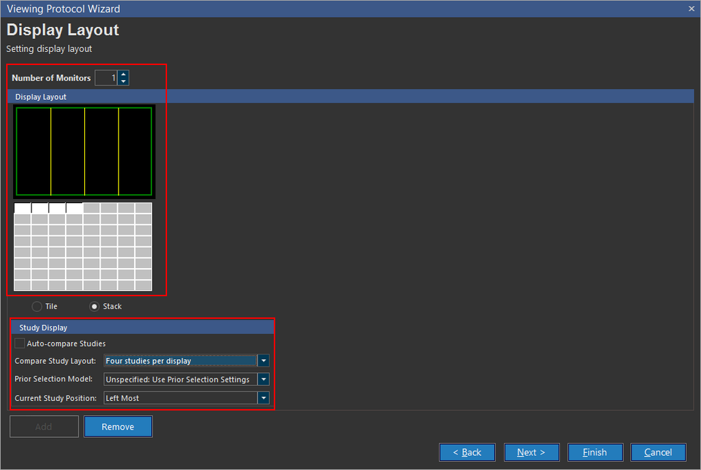
When you select the Current Study Position to be on Top or Bottom, the Current Study Layout option is disabled with the option Two Studies per display selected by default. This means that when you are comparing the current study with its position on the top or bottom, it can only be compared to one study at a time.
Creating a Combined Display layout
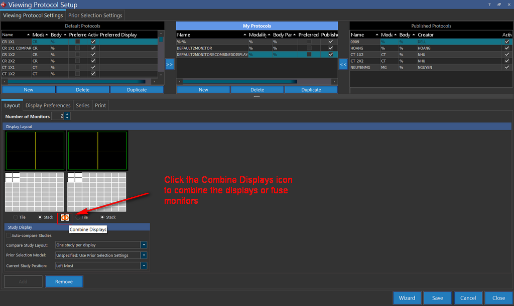
In the Display Layout section, a visual chain link is visible which allows the user to fuse two monitors into one logical display. To combine displays there are a number of conditions, all of which must be satisfied:
- More than one monitor is required for combining displays. You cannot combine displays on a single monitor setup.
- "Compare with prior studies" in Study Display must be unchecked, comparison is not possible when combining displays.
- If you are combining displays on two monitors with different layouts, the layout of the left most monitor will be used for the fuse.
- Displays can only be combined between consecutive monitors which have the same resolution. In case of monitors with different resolutions, the Combine Displays option is disabled.
- When monitors are selected for combining displays, the tile option is automatically selected and stack option is grayed out. 3D MPR is only loaded in stack mode.
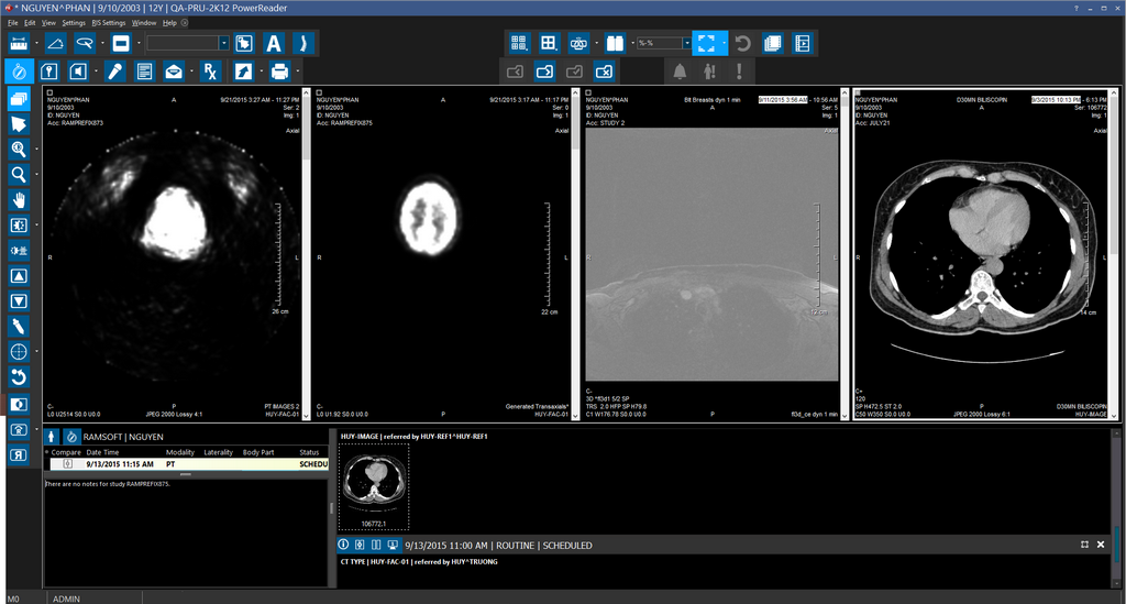
Comparing the current study to a prior study
If you will like to display the current study that is being studied next to the other studies on the screen, check the Auto-Compare option and choose the number of studies that should be displayed per monitor.
In the viewing protocol, the user can define and change modalities for all the monitors displaying the prior studies. This is achieved by right-clicking the monitor icon for the prior study and choosing a modality of the study as shown below. Multiple modalities can be chosen for the prior study. The user is unable to change the modality of the current study.
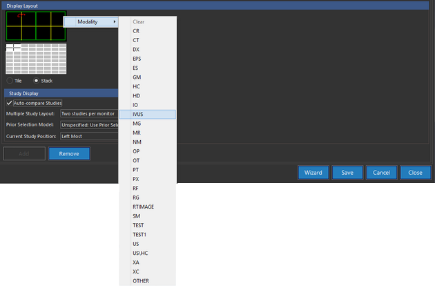
As the user selects a modality for the Prior study, the modality becomes instantly visible in the monitor graphic above.
Select the Prior Selection Model that should be used to retrieve the priors and choose where Current Study Position should be. These changes will also become visible on the monitor graphic above.
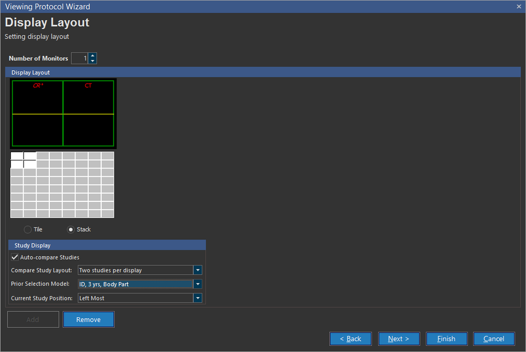
The location of the current study can be identified as the modality of the current study will be displayed with an asterisk (*) next to it. The modalities of the prior studies will be displayed as well.
The Prior Selection Model can be customized in the Settings > Server Settings > Workflow > Relevant Prior Matching tab.
Click Next to proceed to the next step in the wizard.
Selecting display preferences
In this section you need to determine the behavior of some user interaction properties.
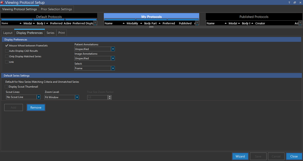
Display Preferences
Checking the Mouse Wheel between Framesets checkbox enables the mouse wheel to scroll into the next or previous frameset or page, depending on the User option for Page Scrolling.
Note: Mouse Wheel between Framesets option disables the ability to hover over a frameset and scroll without clicking on the frameset first.
RamSoft PowerServer is designed to prevent the skipping/dropping of image slices while scrolling through images in Stack/Cine mode.
The Only Display Matched Series option will display only those series which match the Series matching Criteria defined in the View Series Settings Dialogue (The Dialogue and series matching criteria are described in detail in later steps). De-selecting the option will allow the Viewing Protocol to display unmatched series as well.
The Auto Display CAD Results option will display CAD tags when a mammography study is opened (If is option is disabled, the user can view the CAD tags by selecting the CAD button ![]() from the study toolbar). This CADSR icon is visible in the toolbar only when the image is a CADSR object type.
from the study toolbar). This CADSR icon is visible in the toolbar only when the image is a CADSR object type.
The Patient Annotations drop-down menu will display the patient annotations (Patient ID, Accession Number etc) in the viewport. Unspecified option is chosen when the user does not care about displaying the annotations. If the user wants to display the annotations for the study, he will choose the Show option. If the user does not wish to see the display option, he can choose the Hide option.
The Image Annotations menu will display the Image annotations (e.g. SUV value) in the viewport. Unspecified option is chosen when the user does not care about displaying the annotations. If the user wants to display the annotations for the study, he will choose the Show option. If the user does not wish to see the display option, he can choose the Hide option.
Selecting the Link option will enable Plane linking by default. Plane Linking allows linking series within the same study of an active viewport. For more information on Linking, please refer to the topic on Linking Images Across Series.
Default Series Settings
Next you will need to define the default settings for the new matching series and unmatched series
Checking Display scout thumbnail, will display a scout thumbnail for each series in the bottom right corner of each viewport.
The Scout Lines field determines whether scout lines are displayed on the images by default. If the No Scout Line option is turned on, the scout lines will have to be manually turned on by the user, if they wish to view them.
The Zoom Level options determine the magnification of the images displayed on the screen. Fit Window will resize the image so it is fully visible within the viewport that it is being displayed in. Fit Width will resize the image/HC so that the width is maximized inside the viewport. True Size will display images in anatomic size, unless these are x-rays, in which case they will be presented in film size. Choosing the True Size option will activate the True size zoom factor option which can be used to determine the size by which the image will zoom in comparison to the original image. The default is 1.0. The Pixel Size option will render every single pixel when displaying the images. Setting the Zoom Level to Unspecified will not apply a zoom level to the images, and will use the zoom setting in the current presentation state instead. The Auto Size (MG) option will automatically calculate the best-fitting zoom level for all images in the study and apply it. This option is only available if the software has MG license, the study is a mammography study with modality MG and is based on a MG Viewing Protocol. Please see the topic How Do I Use the Auto Size Feature for MG Images? for more details about this option.
Once you have configured all these options as desired, click Next.
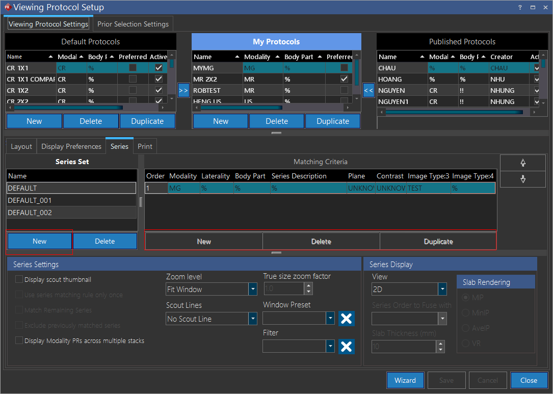
Defining series matching rules

When a user opens the study, the viewing protocol is applied. First, the screen is laid out according to the viewing protocol. Then the series is loaded into the view boxes on the screen. The order in which the series is displayed and how each series is displayed is defined by the series rules created in this section
There are two sections of the Series Order screen. The Series Set table on the right consists of a set of series rules. Each Series Set entry contains multiple Series Matching Rules. All these rules will automatically be part of the Series Set. An advantage of having Series Sets is that it allows a protocol to support multiple scanner types. When the protocol has been chosen, each set of these series rules is examined in order to determine the one that is the closest match for the current study. This is done by comparing each series matching algorithm against each rule set to find the best match. The set which is the closest match is used to display the study. Any series that did not match a rule are displayed at the end (the rules applied to the unmatched series are defined in the Display Preferences screen).
To create a new Series Matching criteria follow these steps:
-
Click the New button under the Series Set table to create a new series set named Default. User can change the name of the series set by clicking the name in the table (e.g. Series Set Two). A name with a length of up to 255 characters is allowed.
-
Click on blank rule in the Series Matching Criteria table and define the parameters for the rules. Click the Save button to save the rule. If you wish to edit the rule you just created, click the View Series Settings button.
-
Click the New button below the Series matching Criteria table and add another rule.
-
Editing an existing rule or creating a second rule for the Series set will launch the Series Matching Criteria dialog.

Here you need to define the criteria based on which various series in the study will be matched. These criteria are usually defined when dealing with mixed modality studies where a certain series might be different from the other series of the study.
Modality and Body part should normally match the values defined at the study level of the protocol. These are normally only changed when dealing with mixed modality studies where series may not have all come from the same modality.
The next field used in the matching is Series Description. This is a tricky field to match, as it is composed of text that is usually manually entered by the techs, resulting in an unlimited range of values. Due to this, a string matching engine has been built into the software. The software will try to match the description that is typed into this field against the Series Description DICOM tag. However, due to the fact that these descriptions can have many variations, the % wildcard character can be entered into the field along with regular text. For example, here are a few different ways to match a description that contains the string T1:
| Pattern | Description |
|---|---|
| %T1% | Any series description that contains 0 or more characters, followed by the pattern T1, followed by 0 or more characters. |
| T1% | Any series description that starts with T1, and is followed by 0 or more characters. |
| T1 | Any series descriptions that only contain T1. |
The following three fields are much simpler. The Plane Type, Laterality and Administered Contrast fields are all composed of drop-down menus. If you want to match a series based on any of those criteria, simply select the appropriate value from the corresponding drop-down menu. If these values are indifferent, the default entries of Unknown and % should be left.
The last two fields Image type 3 and Image type 4 refer to tags created by the DICOM standard that contain additional description fields for complex modality studies such as CT and MR. Once you have selected the matching criteria for this rule, click the Next button.
The options available under drop-down for Image Type 3 and Image Type 4 could be configured and narrowed down using Image Type Setting form.

MG Modality Studies
For MG Modality studies, you cannot add a new set of matching rules. You can create a new Series Set and edit the existing Series Matching Criteria.
For studies based on the MG modality, the Image Type:3 and Image Type:4 matching rules can be assigned from the Display Layout grid. In the Display Grid, you can right-click on a Image View and select the Image Type:3 and Image Type:4 rules.
Note: For the Image Type Settings options to be visible, you to need to have the MG Image Views selected on the Display Layout.
Although any user can view the Series Set and the Series matching Criteria, only a user with Admin privileges can change their order or edit them.
The settings in this screen are the second part of the rule being defined. While the previous screen determines which series to display, this section determines how to display that series.
Series Settings
Checking Display scout thumbnail, will display a scout thumbnail for each series in the bottom right corner of each viewport.
Selecting Use series matching rule only once will match the series rules only once with the series. If the rule matches a series, that rule will be applied to that series and will not be matched any further. For example, if a set of rules have been defined for a series, the first rule will be matched against the series. If the first rule matches the series, the rule will not be matched any further and the system will continue to match the remaining rules against the series.
The Match remaining Series option will apply series settings such as Windows Presets, Presentation State Sharing, etc. to series that do not match any other rules.
Display modality presentation states across multiple stacks option is used to display studies which might have multiple presentation states. This option separates the presentation states and shows them in separate stacks for the viewer. For example, if a CT series contains two presentation states, the option will allow the protocol to create three stacks, first one with just the CT image, second stack with the the first presentation state and a third stack with the second presentation state.
The Exclude previously matched series will apply the rule to only those series that have not been already matched by any previous rules. Thus, if a series set has several rules defined, the protocol will go through them one by one and if the series does not match any defined rules, it will apply the above rule to the series.
The Scout Lines field determines whether scout lines are displayed on the images by default. If the No Scout Line option is turned on, the scout lines will have to be manually turned on by the user, if they wish to view them.
The Zoom Level options determine the magnification of the images displayed on the screen. Fit Window will re-size the image so it is fully visible within the viewport that it is being displayed in. Fit Width will re-size the image/HC so that the width is maximized inside the viewport. True Size will display images in anatomic size, unless these are x-rays, in which case they will be presented in film size. Choosing the True Size option will activate the True size zoom factor option which can be used to determine the size by which the image will zoom in comparison to the original image. The default is 1.0. The Pixel Size option will render every single pixel when displaying the images. Setting the Zoom Level to Unspecified will not apply a zoom level to the images, and will use the zoom setting in the current presentation state instead. The Auto Size (MG) option will automatically calculate the best-fitting zoom level for all images in the study and apply it. This option is only available for a mammography study with modality MG. Please see the topic How Do I Use the Auto Size Feature for MG Images? for more details about this option.
The Slice Order option defines the order in which the slices will be displayed in the viewing protocol. The - To + option while load in the order of last to first slice while the + TO - option will load them from first to last. The Default option will load them in the order they appear in the image.
Choosing a value from either the Window Preset or Filter dropdown menu, will automatically apply that preset or filter to the series as it is displayed on the screen.
Series Display
Finally, the Series Display section with the View drop-down menu is used to create rules for a Fusion (2D), MPR or Slab MPR series. The rules can be saved as a part of the viewing protocol like any other rule. The 2d option is the default option and used when the study being shown is not MPR series. This will be the default view in most cases. The MPR option will be used when displaying any normal MPR series. The Slab MPR option will be used to create an MPR viewport along with a Slab view. If the user chooses this option, the various rendering parameter options become available to the user. The options are MIP (Maximum Intensity Projection), MinIP (Minimum Intensity Projection), AveIP (Average Intensity Projection) and VR (Volume rendering) and will be applied to the viewing protocol according to the view desired by the user. The Slab Thickness option allows the user to adjust the thickness of the slabs used in the MPR.
Fusion can be done within a viewport if the series are PET and CT series. In this case the Fusion option becomes available in the View drop-down menu. Fusion series viewport will be created as a result of PET-CT fusion. Choosing the Fusion option will activate the Series Order to Fuse With drop-down menu. The menu has the various PET series with their order number and the user must choose one of them to be fused with the CT series.
If the Series Matching Criteria has just been created, it might take a few moments for the Series Order to Fuse With drop-down menu to update.
Click Finish to close the dialog and to return to the Series Order dialog.
Defining the order of the series
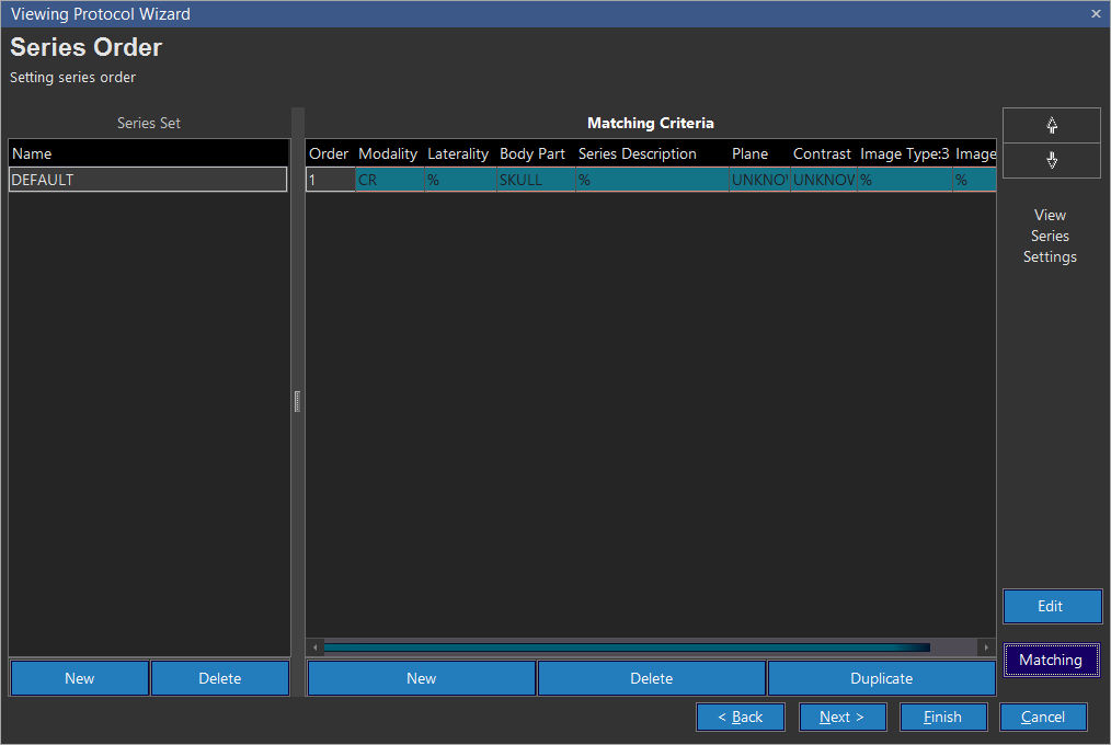
So far you have only created one series matching rule. To create another one, click the New button. If the new rule you want to create closely mirrors an existing one, highlight that rule and click the Duplicate button instead. This will result in all the fields being filled with the values in the selected rule. Now you can just modify the desired values instead of entering them all from scratch.
Clicking the Edit button launches the Series Matching Criteria dialog. You can edit the Matching criteria settings here. Clicking the Matching button displays the current Matching Criteria information.
Once you have finished creating all of the series rules click Next.
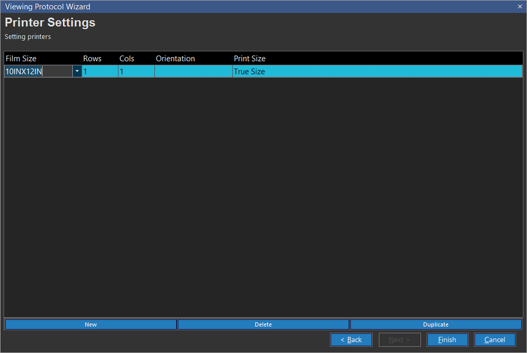
Defining the print settings

Here you can create defaults for the layout of study images on sheet of film. One layout can be created, for each size of film. To add a new layout, click the New button. This will add a new row to the list. Select the Film Size as well as the number of Rows and Columns that should be printed. Next, choose whether the printing should be done in Portrait or Landscape mode. If one image per sheet of film is being printed, the orientation option will be unavailable. In such a case, the system automatically determines the best orientation selection when printing.
The last option to set is the Print Size. This determines the zoom level used when printing the images. If the zoom level should correspond to what is shown on screen, choose the As Shown on Screen option. If the images should always be printed in True Size, that option should be selected. Click the check mark to save the entry. Once you have created all the desired print layouts, click the Finish button and the new protocol has been created.
The following outlines how viewing protocols will operate with reference to studies and priors, multiple-monitor setups and comparison mode:
| Scenario | Action |
|---|---|
| Study has no Priors and both Protocols with Comparison mode and without Comparison mode exist | Choose the viewing protocol with no comparison mode |
| Study has no Priors and only Protocols with Comparison mode exist | Use the protocol with comparison mode |
| Study has Priors and both Protocols with Comparison mode and without Comparison mode exist | Use the protocol with comparison mode |
| Study has Priors and only Protocols without Comparison mode exists | Use protocols with no comparison mode |